Vintage (ish) Sugden Turntable...
Printed From: Progarchives.com
Category: Other music related lounges
Forum Name: Tech Talk
Forum Description: Discuss musical instruments, equipment, hi-fi, speakers, vinyl, gadgets,etc.
URL: http://www.progarchives.com/forum/forum_posts.asp?TID=98120
Printed Date: November 16 2024 at 21:51
Software Version: Web Wiz Forums 11.01 - http://www.webwizforums.com
Topic: Vintage (ish) Sugden Turntable...
Posted By: Dean
Subject: Vintage (ish) Sugden Turntable...
Date Posted: May 02 2014 at 10:20
While clearing out a spare bedroom to make way for a work-from-home office I 'found' an old turntable that I bought back in the early 70s. This turntable was my every-day turntable for all of my teenage life and served me well, but as soon as I had enough spare money to waste on Hi-Fi it was replaced by a succession of turntables, some better, some worse, all of them costing far more than what I paid for this.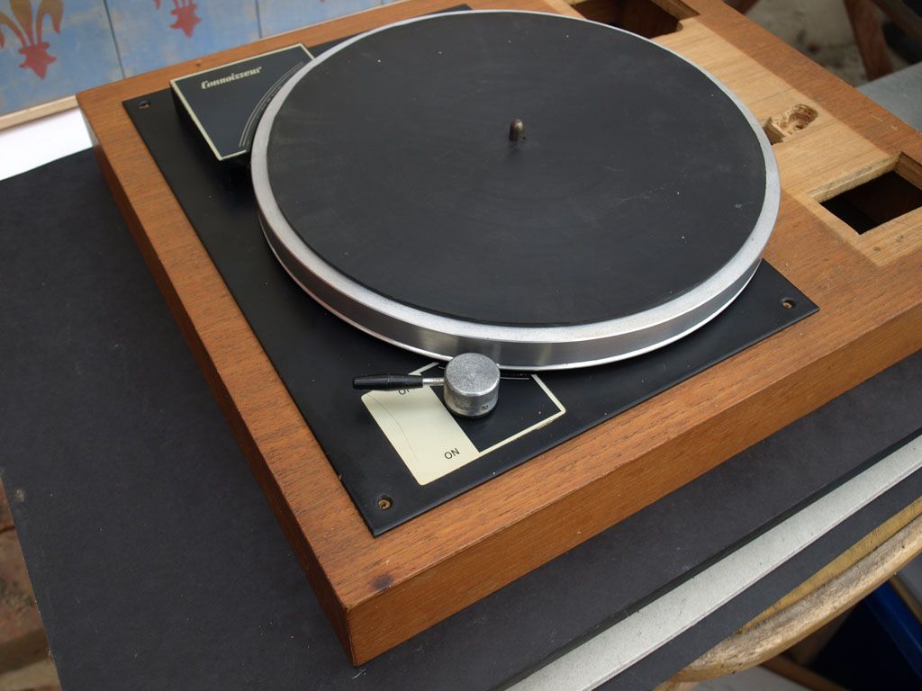 Sold in kit form, the Connoisseur BD1 was designed and made by A.R. Sugden of Brighouse (Yorkshire): 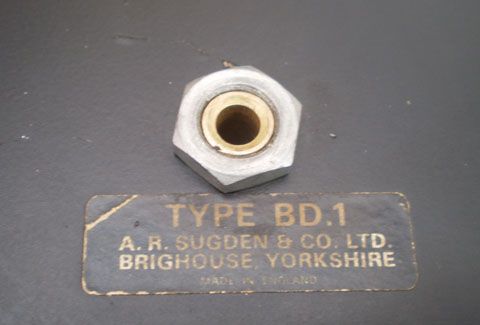 Arnold Sugden (no relation to R.E. Sugden of Sugden Audio btw) was a remarkable fellow. He left school age 14 and became an apprentice undertaker before deciding to turn to engineering. In 1953, with no formal training in mechanical or electrical engineering Sugden set about making high-fidelity turntables, tone-arms and pickups under the name of "Connoisseur" and (since this was in the days before stereo records), he also built his own disc cutting lathe for producing stereophonic microgroove discs to manufacture the records to play on the turntables he was producing. Since he didn't invent binaural discs his name has been a little forgotten in the history of stereo records and record players, (that honour goes to Alan Blumlein of EMI, but EMI never pursued the format), but it was Arnold Sugden who pioneered the use of stereo cartridges, lightweight tonearms and belt-drive turntables, long before the names we know today. So, to my little gem re-discovery. I originally bought this by happenstance, needing a decent turntable I went along to a local hif-fi specialist with the hope of buying a good quality used one but they had nothing in stock in my meagre price-range. Taking pity on me the guy suggested the BD1 and said he'd throw in a used tone-arm that he'd just taken off a brand new Thorens turntable because its owner wanted it fitted with an SME arm. So I left the shop with a small box of bits and a used but brand new Thorens TP13 tonearm, complete with cartridge. All I needed to do was make a plinth and having a carpenter for a Dad that presented no problem. The plinth in the photographs is the original that we made back in 1973, contrary to the fashion in the 70s for big chunky plinths I wanted it to be low-profile but was limited by how Mr Sugden had mounted the motor, in the end we managed to squeeze it all into a plinth that was 2¼" (57mm) high; we mounted the TP13 on an aluminium plate that was once the push-plate from an old door and fashioned the lever for the arm-lift out of an old rotary switch mechanism. Everything was direct mounted to the plinth with no isolation or suspension, I simply stood the whole thing on pieces of neoprene foam that were offcuts from making a wet suit and everything was hunky-dory. 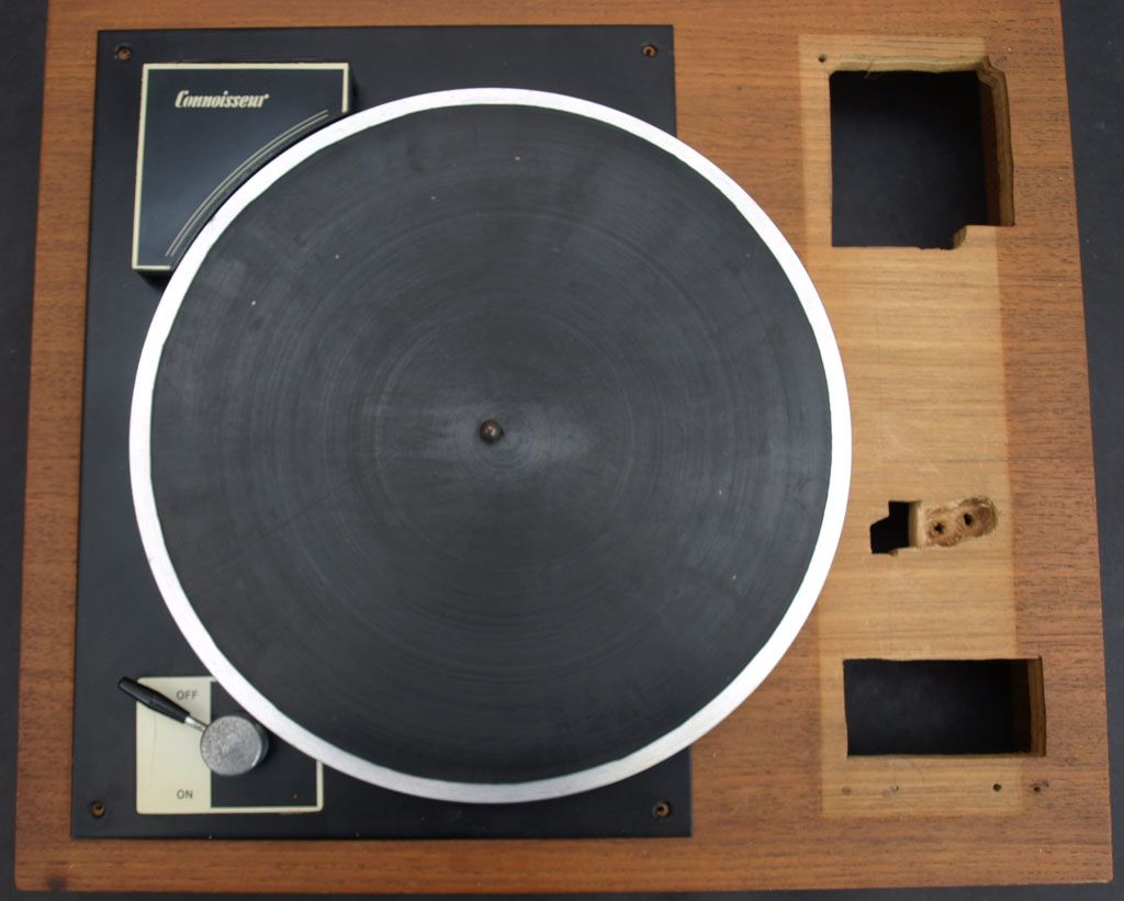 (the eagle-eyed may spot the cigarette-burn on the plinth by the on/off switch, as I said, this turntable serve me through my teenage years, including my 3 years at university - this TT was for chilling and grooving) So there it is, looking a little worse for wear, the drive-belt is missing, the elastic bands that suspended the motor under the platter have long-since perished and the on/off knob has corroded (but that's easily remedied). The tone-arm is safely packed away elsewhere, having long-since been removed from the turntable and kept as a "spare" for my Thorens TD130 turntable that is equipped with the same arm. Out of idle curiosity I gave the 10-inch aluminium platter a flick with my finger and remarkably (considering it hadn't been used for over thirty years) it span for almost two minutes before finally coming to rest. The bearing that Sugden pioneered back in the 1960s is simple - a hardened steel spindle runs in a phosphor-bronze tube that has a single ball bearing in the bottom, this design is still used today, though Rega et al seem to favour ceramic or sapphire balls these days.The motor suspension using three elastic bands on the other-hand I think can be improved, as can the speed selection. Because this was my first turntable I've always been loathed to part with it and it always sounded great, so I am considering re-plinthing project for the summer; this time with complete decoupling between the motor, the platter and the tone arm and all the modern niceties of isolation cones and sound-absorbing foam. Sadly my Dad is no longer alive to help, but I'm sure I've picked-up enough carpentry skills to complete the task. I'm also toying with an idea of driving the motor from some custom electronics that will provide the speed selection and speed control, I haven't worked out the details of that yet, but it could involve an optical sensor to monitor the platter speed, a phase-locked-loop and a power-amp/isolation transformer set-up to drive the motor coils. I'd also consider doing something about the 10" platter but that's more complex as the drive-belt runs around the rim, however something as simple as putting a 3mm 12" acrylic mat on top could be enough. So, perhaps one day it could look like this: 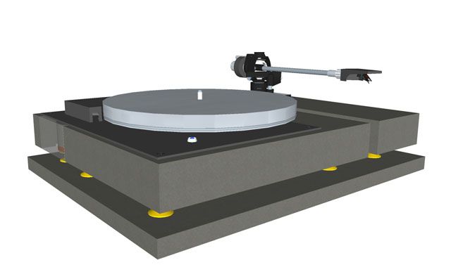 ------------- What? |
Replies:
Posted By: Slartibartfast
Date Posted: May 02 2014 at 11:41
I used to have a Dual that was in a real wood frame.  ------------- Released date are often when it it impacted you but recorded dates are when it really happened... 
|
Posted By: lazland
Date Posted: May 02 2014 at 11:48
What a great post and story! Sounds like a fantastic project to me. ------------- Enhance your life. Get down to www.lazland.org Now also broadcasting on www.progzilla.com Every Saturday, 4.00 p.m. UK time! |
Posted By: Dean
Date Posted: May 03 2014 at 04:53
|
@ Brian - I once owned a Dual too but I wasn't happy with it so I didn't keep it long. @Steve - cheers, I certainly feel inspired to pursue it as I still haven't found a nice piece of timber to make an electric cello out of yet. [I have all the cello-y bits ready to go and I had a piece of willow tree slowly drying in the shed but sadly it dried too fast and split - ho-hum]. In looking into the background of the Connoisseur the more I read about Arnold Sugden the more I came to admire him - he was a "James Dyson" of his day, as well as making turntables and tonearms (with one of the earliest detachable head-shells) and the aforementioned disc cutting lathe, he manufactured pickups, stylii, microphones, electric motors, amplifiers and all the machine tools to mass produce them in a small workshop in a converted Yorkshire church. As an example of his ingenuity, in the mid-1950s he made his first stereo cartridge by mounting two mono cartridges perpendicular to each other connecting them together by a ridged wire link; while I suspect this was more a "proof of principle" rather than a serious attempt at a marketable product, he soon developed a true stereo cartridge.  ------------- What? |
Posted By: Dean
Date Posted: May 03 2014 at 05:54
|
Last night (nothing on TV again after The Blacklist) I gave some more thought to the plinth design:
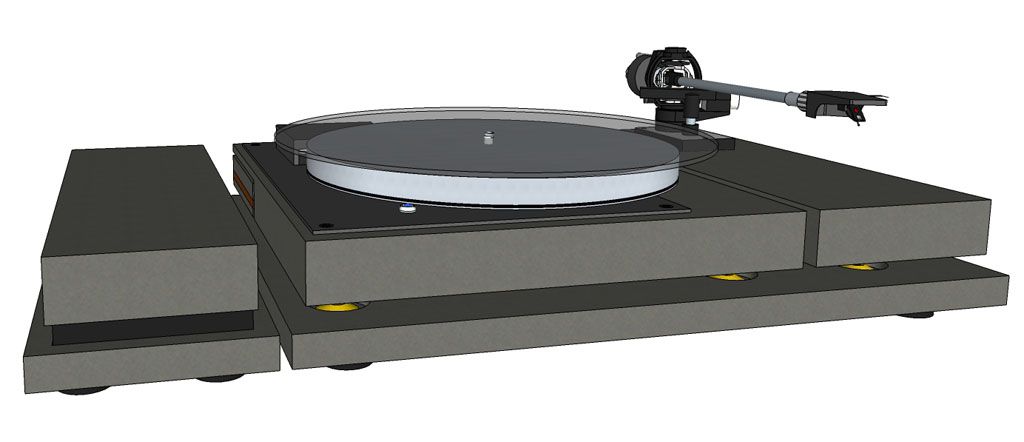 In this Google Sketchup picture you can see the power-supply and speed controller on the left of the main turntable base board and the motor, platter and tonearm all isolated on their own little islands. As you can see I've experimented with placing a 3mm 12" acrylic mat on the platter, not sure whether that's a good idea or not (and it's going to cost me £40 to find out). Here is a 3rd angle projection of the layout: 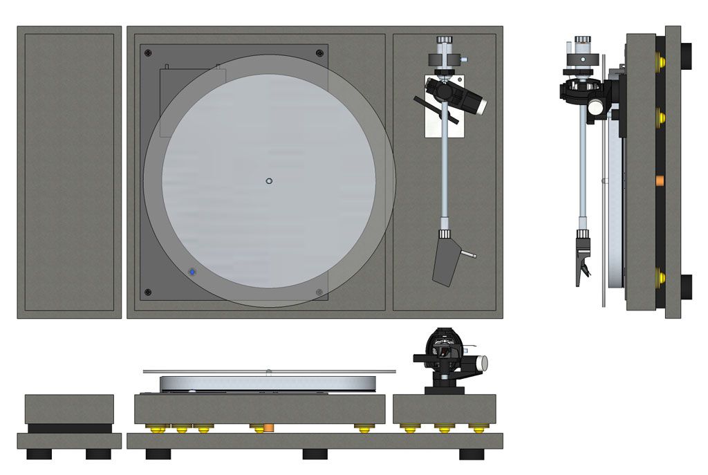 and view of the motor island with an exploded view of the motor mount: 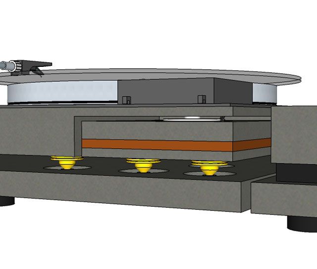 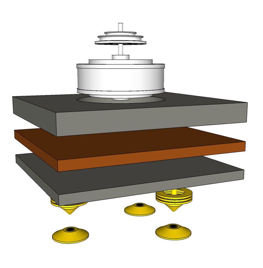 I will admit that 95% of this design is purely aesthetic, I'm neither a fan nor a convert to "isolation" cones and I have used them here simply for looks. All of the true vibration isolation is achieved by the " http://en.wikipedia.org/wiki/Sorbothane" rel="nofollow - sorbothane " foam in the motor-mount sandwich and in the feet of the base-board (which will probably be made from squash balls cut in half or something like that). The cones actually produce a coupling path for vibration, not an isolating decoupling. The purpose of cones is to transmit the vibration out of the thing producing it (in this case the motor) into something more solid and resistant (ie the base-board), which is why they are good for loudspeakers but not for turntables and CD players (or amps). Using them here for the platter and the tonearm is merely a continuation of the motor-mount support so that everything sits at the same height and to impart a degree of rigidity into the set-up. I'm in two minds over the separate island for the tone arm - again this is purely aesthetic as ideally you want a completely rigid link between the tonearm and the disc being played. The advantage of having it separate is so I can change the tonearm without having to make a completely new plinth [my original plinth is such a horrible mess because I initially mounted the TP13 incorrectly and had to move it, then later tried fitting a different arm and had to bodge the cut-out yet again]. I'm still thinking about the electronics and it all seems very do-able. The motor is an 110V AC 50Hz motor spinning at 375rpm. If I use the Sugden's 33rpm pulley I need to make this motor spin at 506.25rpm to play 45s which means driving the motor at 67.5Hz. Obviously I cannot alter the mains frequency so I will need to generate my own 50Hz and 67.5Hz signals and boost them up to 110V to drive the motor. This is a lot easier than it sounds and works out quite nicely. In doing the maths I have calculated that a simple 240V to 10V step-down transformer wired backwards will produce 110V from a 5V(rms) input. The reflected impedance of the motor calculates out at 7.6ohms so a simple 4W audio amplifier that can produce a 5V rms output into an 8ohms load is all that is needed to drive the transformer. Such an amplifier is the TDA2030A, which can be picked up from eBay for a couple of quid:  Working out how to generate a super-stable 50Hz and 67.5Hz signal is the next hurdle to overcome and I've a few ideas for that based upon generating a much higher frequency (which is easier to make stable) that is phase-locked to the platter spin-speed and then dividing it down to produce the low frequency sine-waves, but there is still some thinking to do yet before I settle on a final design. This is at the "thinking out loud" stage I'm highly receptive to all inputs... so if anyone has any thoughts, ideas, comments and suggestions I'm all ears. ------------- What? |
Posted By: Dean
Date Posted: May 09 2014 at 18:02
|
Getting close to the final design now. Added switches for the power, speed and arm raise/lower and a heat-sink for the motor-drive amplifier. I've also corrected the tonearm alignment geometry and recessed it into the plinth as it is on my TD130. 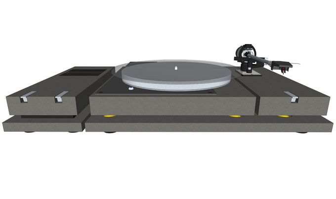 I intend to make everything from 6mm MDF sheets that will be laminated together to make the varying thicknesses of material in the design, this way I can produce recesses in the timber without using a router. It also means I can get the panels made using a laser cutter if I can find somewhere local that will do it for a reasonable price. Otherwise it will be me, a jigsaw and a dremel... that a lot of time and patience. I've more or less sorted the speed control circuitry: 331/3 rpm = [11.0592MHz Xtal] ->[Divide by 128]=(86.4KHz)->[Divide by 216]=(400Hz)->]Divide by 8]=50Hz 45 rpm = [11.0592MHz Xtal] ->[Divide by 128]=(86.4KHz)->[Divide by 160]=(540Hz)->]Divide by 8]=67.5Hz The last divider stage is a crude 3-bit DAC that converts 400Hz square waves into 50Hz sinewaves, this goes through a filter to smooth-out any rough edges and then to the power amplifier and step-up transformer. In theory that should be enough to produce a signal to drive the motor that will be significantly more stable than the mains that the old version of the turntable used. I'm working in a method of measuring the platter speed and using that as the "compare" signal in a phase-locked loop. I intended to look at using the laser diode from an old DVD drive but on taking one to pieces I spied a disc position optical sensor that is used in the Lightscribe circuitry which seems a far better proposition because it is a lot less bulky and will fit unobtrusively under the rim of the plater. This sensor will pick-up strobe marks on the underside of the platter and convert them to a square-wave. A disc spinning at 331/3 rpm does 1 full revolution in 1.8 seconds, therefore to produce a 400Hz signal that I can phase-lock to the 400Hz in the speed control circuit 400 ticks will need to pass over the sensor in one second. So in 1.8 seconds 720 ticks will pass over the sensor, which means that the ticks will be spaced every ½ degree. At first glance that seems to be very narrow, especially when you think back to the little plastic protractors we used at school that had graduations once every 1 degree:  But on an 10" platter (which has a circumference of 31.42 inches) ½ degree is 1 tick every .04" (or just over 1mm). Anyway... long explanation short - I used Excel, Gerber-viewer and Adobe Illustrator to create a 10 inch diameter disc with 720 strobe ticks and printed it on a 1200dpi printer, and it looks fine. If I could get that etched under the rim of the platter that would be even better. ------------- What? |
Posted By: yam yam
Date Posted: May 09 2014 at 20:59
|
LOL! My first 'hi-fi' turntable was also a Connoisseur BD1. |
Posted By: Dean
Date Posted: June 17 2014 at 14:34
|
^ I genuinely don't have a preference either way - Vinyl, CDs, mp3s - as long as the music's good and everything sounds clean and loud I'm going to be as happy as a pig in very comfy chair. That we can get music out of scratches on a disc of PVC, using nothing more than a pin and a cone of paper is magic enough, converting that simple mechanical transformation into electrical signals and back again is a piece of cake by comparison. ~~~~~~~~~~~~~~~~~~~~~~~~~~~~~~~~~~~~~~~~~~~~~~~~~~~~~~~~~~~~~~~~~~~~~~~~~~~~~~~~~~~~~~~~~ Brief update. The project is moving along, albeit slower than I would have hoped. The idea of laser cutting was quickly discarded once I'd calculated how much it was going to cost to cut three 1.2m sheets of 6mm MDF, so I crudely bolted a Rotozip Rebel spiral saw to an old wardrobe door to form a cheap and cheerful router table so I could accurately cut-out the dozens of pieces of wood needed to make the plinth. They are all glued-up now and waiting to be sanded, filled and sanded again before painting. I've "Macgyvered" a simple sanding table using the same wardrobe door as before but now fitted with an electric drill and a hook'n'loop sanding disc pad - just waiting on a delivery of sanding discs from Amazon before work can continue. I'm also toying with the idea of making a pantograph attachment for a Dremell so I can engrave legends on the three switches, and perhaps a snazzy logo on the plinth itself, but that's a scary prospect because one slip and it's goodnight Vienna to weeks of work. Next stage is to produce the brass boxes that house all the electronics - aluminium would probably be easier to work with but I can't braze that and brass leaves me the option of polishing and varnishing it, which could look cool (or it could look really tacky). I've bread-boarded most of the electronics and that seems to work as planned, in the end I used the TDA2030A in BTL configuration because the size of step-up transformer I just happened to have lying around in a drawer - if I wasn't such a tight-wad I'd have splashed out on a toroidal transformer of the right turns-ratio, but this works just fine. The electronics for the "soft-touch" switches works and I really like the piano-key style lever switches I've designed - since the Connoisseur is piece of a late-60s/early-70s design I wanted the switches to resemble the keys on an old cassette player yet still look modern. I've still got the arm-lift to sort-out as I want that to be operated by a "soft-touch" switch too - it will probably be based upon those http://www.amazon.co.uk/Servo-Plane-Helicopter-Futaba-Hitec/dp/B009REPY06/ref=sr_1_1?ie=UTF8&qid=1403032900&sr=8-1&keywords=servo" rel="nofollow - cheap plastic servos that are used in R/C toys even though the control circuitry for those is more complicated than it really needs to be just to pull on the Bowden cable that operates the Thorens arm-lift. My dear wife has come-up with a brilliant idea for the 3mm acrylic mat that I wanted to use to increase the size of platter from 10 to 12 inches - no clues or spoilers as to what that idea is until I post pictures of the finished TT.  That's about it so far. ~~~~~~~~~~~~~~~~~~~~~~~~~~~~~~~~~~~~~~~~~~~~~~~~~~~~~~~~~~~~~~~~~~~~~~~~~~~~~~~~~~~~~~~~~ Being an Engineer by trade and being equipped with an engineer-type mind means that when I take something apart it's because I want to know how it works, and how it was made, and more importantly, how it goes back together. It also means that I'm plagued by NIH syndrome ( http://en.wikipedia.org/wiki/Not_invented_here" rel="nofollow - Not Invented Here Syndrome ) - this results in seeing how something works and immediately wanting to fix, improve or simply change it to make it different. If you've ever wondered why designs keep changing it's more often than not NIH-S in action. 20 years ago I built a test jig and wrote some software to test a video amplifier, we still make and sell that video amp and over the years its been handed over to different engineers and technicians to maintain and look after - every one of them has re-written the test software, not because it didn't work or was buggy, but simply because of NIH-S. So, since starting this little project I've had dozens of ideas running around in my head that I'd like to have tried but decided that I wanted to keep as much of the original Arnold Sugden Connoisseur hardware as I could. The only thing I've discarded so far is the on-off switch and three perished elastic bands so it will still be able to carry the Connoisseur badge with some degree of integrity. Therefore ideas of replacing/upgrading the motor were put to one side, along with thoughts of replacing the bearing, the drive pulley and the 10" platter, because if I'd done all that then the only original thing left would have been the metal platform itself ... and to be honest I'd quite like to have replaced that too with one that was the full-width of the plinth. The outcome of all that is, once this is finished (and it will get finished) I'd quite like to design and build a brand new turntable from scratch. I would also like to make my own tonearm even if the precision required is probably beyond the my metalworking capabilities and that of my poorly equipped garden shed workshop - but the physics, mathematics and geometry behind their design isn't hard. When you see what little "engineering" goes into a Rega, Linn, VPI, Pro-ject or Music Hall turntable the idea of building one yourself doesn't seem such a challenge - with turntables and tonearms it doesn't take a genius to see that less is more. ------------- What? |
Posted By: Finnforest
Date Posted: July 24 2014 at 18:29
Dean, thought you might enjoy.....Tonight just might be one of those nights...  |
Posted By: Dean
Date Posted: July 24 2014 at 19:36
Oh My - a Garrard auto-changer... with an 8-track.  While on vacation last week we dropped in on a friend of Debs who'd just retired and moved down to Somerset. While they were Debs friends I'd never actually met her husband before, after showing us around their new house he took us to a room above his garage which was going to be his new "man cave" that he was kitting out as a listening room with all new equipment (which had only been delivered the previous day and was still boxed and unopened). Rather than show me the expensive audiophile contents of the boxes he instead pulled a sturdy and very professional looking flight-case from behind the sofa. "Would you like to see my retirement present from work?" he asked. Puzzled but curious, I nodded.... this was inside: 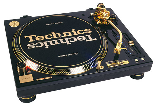 ..that's a Limited Edition Technics SL-1200GLD Direct Drive Turntable. *gulp* ... a $2,500 retirement present - somehow I don't think I'll be getting anything like that when I retire. I glanced around the room for his record collection but couldn't see anything so assumed it was all still boxed up after his move. To make conversation I told him I'd just bought the 180gm 40th anniversary Dark Side of the Moon. "I've got an older version of that" he said -- I replied that I had several copies, including a first edition. He didn't look impressed. He opened a cupboard to reveal his entire album collection ... of around 10 albums (I didn't count them) and most of them were hifi test albums, so it was my turn to look unimpressed. Until that is he reached in and very carefully pulled his copy of Dark Side ... a 1978 original half-speed master recording from Mobile Fidelity Sound Lab ...only 25,000 of those were ever produced and they are said to sound amazing. For all the very expensive equipment in that room, including the SL-1200, I would have happily walked out of there with that under my arm.
------------- What? |
Posted By: Catcher10
Date Posted: July 24 2014 at 19:49
|
I have seen a few of these custom built tables, this one the plinth from a slice of mesquite root ball.
The builder had to let the slice dry for about 18 months. Tonearm is a LAD, similar to Jelco arms, LAD was produced in Wales and to my knowledge they no longer are in business. He used a Marantz 6300 motor, isolation feet from a Technics I think. Some nice CNC work on this table for motor base and knobs and such...for sure a pc of eye-candy. Rather cool looking too.. 
Enjoy your build Dean. -------------   
|
Posted By: Finnforest
Date Posted: July 24 2014 at 19:54
|
^^Holy cow.....so when do we knock over his place? I'll grab the album you can drive the getaway.... My first turntable was a Technics but it didn't look anything like that....I remember the Mobile Fidelity stuff. Had a few albums, and I think I still have a couple CDs. "Tea for the Tillerman" comes to mind. |
Posted By: Finnforest
Date Posted: July 24 2014 at 20:03
Oh I like that one too Jose. If I keep following this thread I'm gonna want an album collection again. Not good since I gave away all my vinyl! 
|
Posted By: Dean
Date Posted: July 24 2014 at 22:18
I agree that it is very nicely made but it's not to my tastes. I think we're going to have to acknowledge that our ideas of cool in the turntable world are wildly different.  ------------- What? |
Posted By: manfromstoke
Date Posted: August 12 2014 at 07:52
|
To say I'm impressed would be a understatement. Be great to hear and see the end result. What an interesting chap Arnold Sugden was! Still have a passion for HiFi born from listening to my parents all in one system comprising Garrad 301, leak valve amp mounted inside a walnut cabinet and if memory serves the inbuilt speakers were GEC. Things moved along and like many I did the HiFi trail of Dual 505, Rega2 ,Thorens TD150 and then eventually got bit by the 'Graduated increments of pitch with respect to time brigade', thus became a disciple of Linn. Had a long period of HiFi abstinence from about 1998-2010 but now enjoying the system once more. For me nothing can quite match the ritual of picking up that black round thing placing it on the platter and lowering the arm while watching that cantilever take the strain. Reading your thought process leads me to believe the end result could be something special. Please keep us updated. ------------- A fool can ask more questions than a wise man can answer. |
Posted By: Dean
Date Posted: August 12 2014 at 11:36
|
Thanks for the words of encouragement Nee. The build is progressing, albeit slowly, I hardly seem to have any spare time to work on it of late. The woodwork had its first coat of paint at the weekend (a rather dark shade of moody blue) - that's got to be sanded, inspected, retouched and painted again before copious coats of clear varnish are applied. It will then sanded and buffed to a mirror finish before I'm going to be happy with it. As I said, a lot of this is going to be about the aesthetics - this has got to look better than good - so I'm having to reign-in my normal impatience to see the finished turntable in action to get it just as I want it. I'll post some work-in-progress pics when I've got something worth showing. ------------- What? |
Posted By: progbethyname
Date Posted: August 20 2014 at 11:05
This is a great story, Dean. Thank you. Pretty interesting. All that gear with only one desirable record...pretty damn good one at that. ------------- Gimmie my headphones now!!! 🎧🤣 |
Posted By: Gerinski
Date Posted: August 22 2014 at 01:29
|
Congratulations Dean with this exciting project! I'm no engineer but the only thing which looks a bit weird, as you have yourself pointed out, is having the arm mounted in a separate body than the platter. Both will need to be joined in some precise manner in order to preserve the alignment. I understand the argument about having the possibility to change the arm type without having to screw the body top, but what about simply having a sub-top for the arm in the same body as the platter, which could be replaced if necessary by a different one?
|
Posted By: Dean
Date Posted: August 22 2014 at 05:50
Having the tonearm separate is a common feature of high-end turntables: 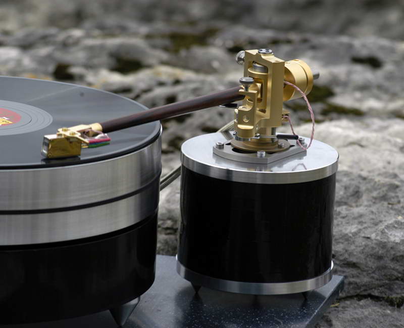 While there is no direct connection between the pivotal point of the tonearm and the spindle of the platter the weight of both plinths acting through the spikes should be enough to ensure a degree of rigidity between them. If the vibration in both is kept to a minimum then the complete decoupling should not present a problem, (given the wavelength of acoustic vibration is measured in metres not millimetres any residual vibration is sympathetic anyway). I can always add weight to reduce vibration and increase rigidity. The obvious advantage is the geometry can be adjusted which is something that is difficult to achieve on a one-piece plinth, while I took measurements from my Thorens TD160 to get the approximate position of the arm, I cannot claim my measurements were in any way accurate so some tweaking will be necessary. But as I said, from the perspective of this design it's purely aesthetic. ------------- What? |
Posted By: Dean
Date Posted: October 27 2014 at 04:48
|
Quick update... Long way to go yet, progress has been incredibly slow due to other priorities, such as The Good Lady deciding that, since The Daughter is getting married next year, the entire house inside needs completely redecorating, and the garden needs sorting out, and the patio, and the car-port/veranda, and probably much more besides, (it's been a while since I consulted the extensive 2-page "to do list" that appeared on the 'fridge door several months ago). Quite why this should be is beyond my simple male-mind to comprehend, but she has spoken... So... Back in June the woodwork looked like this: 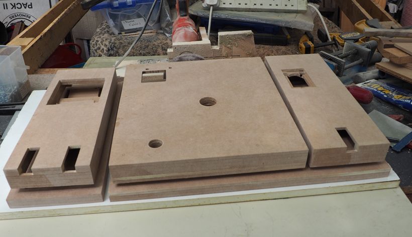 And now, after receiving multiple coats of paint it looks a little like this: 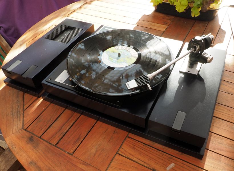 This is just a "dry-fit" of all the major parts to ensure it all fits together nicely. The paintwork will require more sanding and several coats of clear lacquer before being buffed to a mirror finish, then a coat of anti-static because at the moment it attracts dust and cat-hair like crazy. I've still got all the metalwork to do and I've yet to transfer all the breadboarded electronics to PCB but hopefully those can be accomplished over the winter-months. Onwards and upwards.
 ------------- What? |
Posted By: Catcher10
Date Posted: October 27 2014 at 10:58
|
sweet -------------   
|
Posted By: Meltdowner
Date Posted: October 27 2014 at 14:18
|
Great work Dean! By the way, what's that thing on the top left side for? |
Posted By: Argonaught
Date Posted: October 27 2014 at 16:14
If you mean on the top left of the table itself (not the separate unit to the left of it), this must be a slat that covers the motor and pulley assembly .. right?
|
Posted By: Meltdowner
Date Posted: October 27 2014 at 16:21
|
^ No, I meant the unit to the left. I didn't noticed it was separated, and now that I think of it, how do those two buttons work? |
Posted By: Argonaught
Date Posted: October 27 2014 at 16:53
| ^ That would be his power supply (I think I am seeing a heat sink on it?), and speed control circuitry. He wants it separate so as to decouple any 60 Hz vibration and maybe inductive currents from the table itself. |
Posted By: Dean
Date Posted: October 28 2014 at 06:04
Correct, but here in "the rest of the world" we used 50Hz. Unfortunately the motor is an 110v AC motor so that source of noise is still present in the turntable plinth. I could replace that with a DC motor but I want to retain all of the Connoisseur components, including the motor. I've kept the power-supply and speed control circuit separate more for aesthetics than any practical consideration - it also means that at some later date I can replace that box with a different design if I want to.
The two buttons are "Stop/Start" and "Speed Select". Power to the box is "always on" so that the speed control circuit and motor drive amplifier is always at working temperature, which improves stability. Therefore the "Start/Stop" simply gates-off the drive signal to the motor drive amplifier, and the "Speed Select" switches the clock circuit divider to divide the quatrz controlled master clock by the appropriate value. I originally intended them to be touch switches then changed my mind and redesigned them to be lever style push-buttons like a piano key. However, I didn't want them to latch mechanically so used a non-latching sub-miniature micro-switch and designed the latching function part in electronics. This is very similar to how the soft-touch "push-on/push-off" foot-switch on Ibanez and Danoelectric effects peddles work. For those who understand digital electronics, the circuit looks like this: 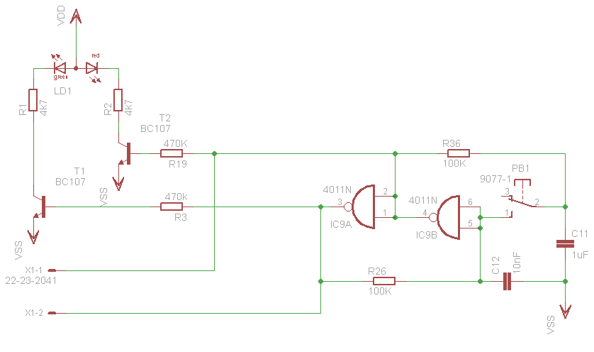 ..which is a simple toggle-latch that lights either a green (ON) or red (OFF) LED - the two output lines (X1-1 and X1-2) go to the Speed Control circuit. And mechanically, it looks something like this: 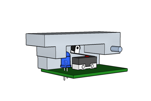 (the LED is bi-colour) A similar piano key circuit is used to raise and lower the tonearm. In the photograph the arm-lift is not yet fitted as I'm still working on the electro-mechanical part of the design. ------------- What? |
Posted By: Argonaught
Date Posted: October 28 2014 at 07:00
Indeed so; and neither do you all use split-phase home power supply :)
Clever stuff. Is this how these things work in mass-produced equipment as well, or it's Mr. Dean's ingenuity shining through?
I do know one or two things about semiconductors, but from an different angle: what to make them from. The 4011 are metal oxide NAND gates that remain latched in a certain position until the next signal? Meltdowner is studying electronics, so he should understand more. [/QUOTE]
|
Posted By: Meltdowner
Date Posted: October 28 2014 at 08:04
^ I studied Computer Engineering, which had a basic Electronics class
and I was really bad at it, probably because one professor didn't say
anything the whole class and the other taught like we were specialized
in Electronics. So I ignored those classes and learned everything from
scratch by myself and after three months of intensive studying, I
finished with 55% and it was the second best grade  Anyway, if I understand correctly, if the switch PB-1 is at 3 the red LED is on and if it's at 1, the green LED is on and somehow those NAND gates will indicate the speed control circuit to start and at what speed. Can you correct this Dean? 
|
Posted By: Argonaught
Date Posted: October 28 2014 at 09:38
| ^ speaking out of turn (again!), I believe that this piece of circuitry is an electronic toggle switch only. To control the AC motor rpm, he needs to feed it a certain frequency. So, there will have to be another circuit that would rectify and smoothen his mains AC into a more or less DC and then get something to flip-flop its polarity continuously at the desired frequency. I won't say any more, because I am already picturing myself a bridge, followed by an LC filter, followed by an oscillator, tuned to the frequency he wants, but Dean will likely do it in a less old-school way. |
Posted By: Dean
Date Posted: October 28 2014 at 10:47
It has been a long established practice in audio circles to keep power amps permanently powered as they can take up to 20 minutes to settle down to their working temperature and bias levels. You wouldn't do a comparative listening test on cold equipment for example. Certainly when we design, build and test them any adjustments are made after their ambient temperature has stabilised so it would be logical to allow a similar time to elapse before using it. Since the drive circuit for the motor in my tt design is simply an audio power amplifier extending that practice to this turntable also seems logical. [My NAD 3020A has been switched on since I first bought it back in 1982 and only gets switched off when I move house or there is a power cut. It is a testament to the NAD design engineers that it has not given me any trouble whatsoever in 32 years of (literally) continuous use. Personally I don't know if it makes any difference to the listening pleasure but not power-cycling an amp puts less strain on the components.] Of course most remote-controlled equipment has a "standby mode" that switches off some of the circuitry but keeps the IR link powered so you can switch it back on. ------------- What? |
Posted By: Catcher10
Date Posted: October 28 2014 at 11:29
|
There are tons of online debates about "power on or power off".....What I think people miss is the point that Dean makes is that it is not about "I leave my amp powered on 24/7 because it sounds better.....". I also have a NAD integrated amp and will power it ON on Friday and not turn it off till Sunday late evening. It has a "standby" mode so I am not "powering it off" when I hit the power button. But for 3 days it is on 24/7......During winter months when I listen a lot, I leave it on for months. I do turn off my DAC since it has a tube, a tube only has so many hours. Then you have the people that argue you have to turn it off.....well my refrigerator has been running ON for 15yrs in my current house and I can count on one hand how many hours it has been off in those 15yrs, and it still keeps my food cold and safe to eat today.... Habit just keeps me from leaving my gear on 24/7, I hear my dad in my head screaming at me to "turn it off...your wasting electricity!!" -------------   
|
Posted By: Dean
Date Posted: October 28 2014 at 12:04
|
Hmm, this is going to be a test of my powers of explanation

Oh man, your Lecturers/Teachers need their arses well and truly kicking, that's abysmal. Their role is to teach everyone in the class. Admittedly linear/analog electronics is a bit complicated even for the basic stuff, but logic/digital electronics isn't exactly difficult to teach.
The switch is a push button, when pressed it switches to 1 but when release if springs back to 3. Without the logic gates I would have to permanently hold my finger on the switch to select 45rpm. The two NAND gates remember that the push-button has been pressed and hold the circuit in the required state until I press it again. In that circuit schematic you'll notice that the inputs of the NAND gates are wired together, therefore I am using them as Inverters or NOT gates ... a "1" on the input will set the output to "0" and a "0" on the input will set the output to "1". The circuit works like this:
One way to look at this is C11 and C12 are the circuits "memory" - C11 remembers the "1" or "0" on IC9b's input and C12 remembers the Inverted level on IC9bs output. Therefore C12 will always be in the opposite state to C11: when C11 is "1", C12 will be "0" and when C11 is "0", C12 will be "1". The push-button switch is used to overwrite C11 with the voltage remembered by C12.  I hope that isn't too confusing. I hope that isn't too confusing.
Yes, the circuit above is only part of the full circuit and is only the latching circuit for the switch. I've drawn it in a non-standard way to make the component layout easier in the schematic, essentially it is a cross-coupled bistable "flip-flop" that you'd normally seen drawn like this: 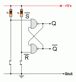 In that configuration I would need two push-buttons, one to "SET" the latch and one to "RESET" the latch. As explained above, the capacitors in my circuit allow me to do that with one push-button (push-to-set, then push-to-reset). I'll not show the complete circuit diagram for the speed controller since that is currently my unprotected IP and I'm not in the mood to share  However, I will try and explain the principle: However, I will try and explain the principle:The Q and Q/ outputs are used to set the divide ratio of a http://www.nxp.com/documents/data_sheet/74HC_HCT4059_CNV.pdf" rel="nofollow - CD4059 (programmable divide-by-n counter) to either 216 or 160. The clock for this counter is generated from an 11.0592MHz quartz crystal wired to a http://www.fairchildsemi.com/datasheets/CD/CD4060BC.pdf" rel="nofollow - CD4060 14-stage ripple counter that is preset to divide that crystal frequency by 128. Together these two counters will produce a clock of either 400Hz or 540Hz depending on the state of the speed-selector latch. This is then divided by 8 to produce the 50Hz (or 67.5Hz) needed by the motor. The reason why I do this in three stages is so I can insert a phase-locked-loop (PLL) into the circuit that monitors the platter speed and adjusts the clock frequency accordingly. Rather than use a filter to produce a sine-wave I am using a DAC to create a pseudo sinewave from a binary sequence. Precisely how I do this will remain a secret for now, because if I ever find myself out of work with a hefty redundancy cheque, I would like the opportunity to make this control circuit commercially and sell it to owners of Linn, MH, Rega and Pro-ject turntables.  ------------- What? |
Posted By: Padraic
Date Posted: October 28 2014 at 12:25
|
Cool project Dean. |
Posted By: Meltdowner
Date Posted: October 28 2014 at 12:59
Not confusing at all, don't ever doubt your powers of explanation  I didn't know what the capacitor was (it was not on that class' program  ), but I understood how it worked when you explained. ), but I understood how it worked when you explained.I also didn't noticed about that NOT gate with NAND's, although I immediately remembered about the NAND gate being a universal gate. Thanks for the lecture  |
Posted By: Argonaught
Date Posted: October 28 2014 at 17:39
|
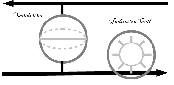
^ What an illuminating discussion! Speaking of the Art of Explanation ... I remember reading a late 19th century book on electricity. People had been already using electricity in earnest, but had no idea what it was. Engineers used hydraulic analogies to describe the rules of behavior of electric current: voltage was pressure, current was the flow of water, resistance was a narrowing section of the pipe, the power source was a water pump etc. To help visualize how a capacitor (aka “condenser”) works, they depicted it as a bladder tank; induction coils were like water wheels J I’ve reproduced the pic as I remembered it. As you can see, the capacitor fills up with water on one side until its pressure is canceled by the counter-pressure from the stretching rubber diaphragm in the middle. Once you remove the inlet pressure, the diaphragm will contract and discharge the water back into the pipe.
It occurred to me that you could even explain the diode (= check valve) and the transistor (= a garden hose faucet with spring-loaded handle) in these hydraulic terms! |
Posted By: Meltdowner
Date Posted: October 28 2014 at 18:31
^ Great analogies, really easy to undestand. I use all kinds of analogies to learn things, most of the stupid that only I can understand, but it works  |
Posted By: Catcher10
Date Posted: October 29 2014 at 10:30
very cool! -------------   
|
 Catcher10 wrote: